Blog

BEAMIT and the InShaPe Project: Boosting Productivity and Unlocking New Horizons in Additive Manufacturing
Authors: Federico Uriati (Beamit), Michele Caldarini (Beamit), Robin Prudlik (Oerlikon)
Additive Manufacturing (AM) is experiencing rapid evolution, and the European InShaPe project is a concrete example of this progress.
BEAMIT, as a leading player in the sector, has played a key role in demonstrating the success of integrating beam shaping into the LPBF process.
An industrial gas turbine swirler was selected as a critical component, specifically designed to optimize the mixing of fuel and air, improve combustion, and reduce emissions. Its complex geometry and the requirement to withstand high temperatures and mechanical loads make it an ideal test case for additive manufacturing – featuring shapes that are unachievable using conventional methods. Early trials on this application were conducted at the TUM Garching facility using a beta prototype system equipped with a 2 kW laser and advanced beam shaping capabilities.
This preliminary phase, as highlighted in the dedicated InShaPe blog post (Metal Additive Manufacturing – Adoption of Innovative Beam Shaping Technology for Greater Efficiency and Sustainability), focused on testing different beam profiles and process conditions to maximize productivity and ensure the manufacturability of complex geometries like the swirler. The research provided valuable insights into process stability and performance, laying the groundwork for the full-scale testing that followed.
Maximizing Productivity with Beam Shaping
One of BEAMIT’s most striking achievements was the significant increase in productivity made possible by integrating beam shaping into the LPBF process. By developing optimized process parameters, BEAMIT achieved a build rate of 86.4 cm³/h, representing a 5.7x increase compared to the standard Gaussian beam at 40 µm layer thickness.
This productivity gain was achieved without compromising material quality, with tests confirming a material density exceeding 99.8%, indicating high internal quality and process reliability.
The remarkable results achieved in InShaPe were the outcome of intensive research and multiple iterations aimed at fine-tuning the beam shaping parameters.
A wide range of configurations were tested, combining:
- Different beam shaping profiles, including ring, chair, and teardrop shapes, to modulate the energy distribution and improve melt pool stability.
- Variations in laser power (from 700 W to 1300 W), scanning speed (1200 to 3000 mm/s), and hatch spacing (0.1 to 0.15 mm) to balance deposition rate with material integrity.
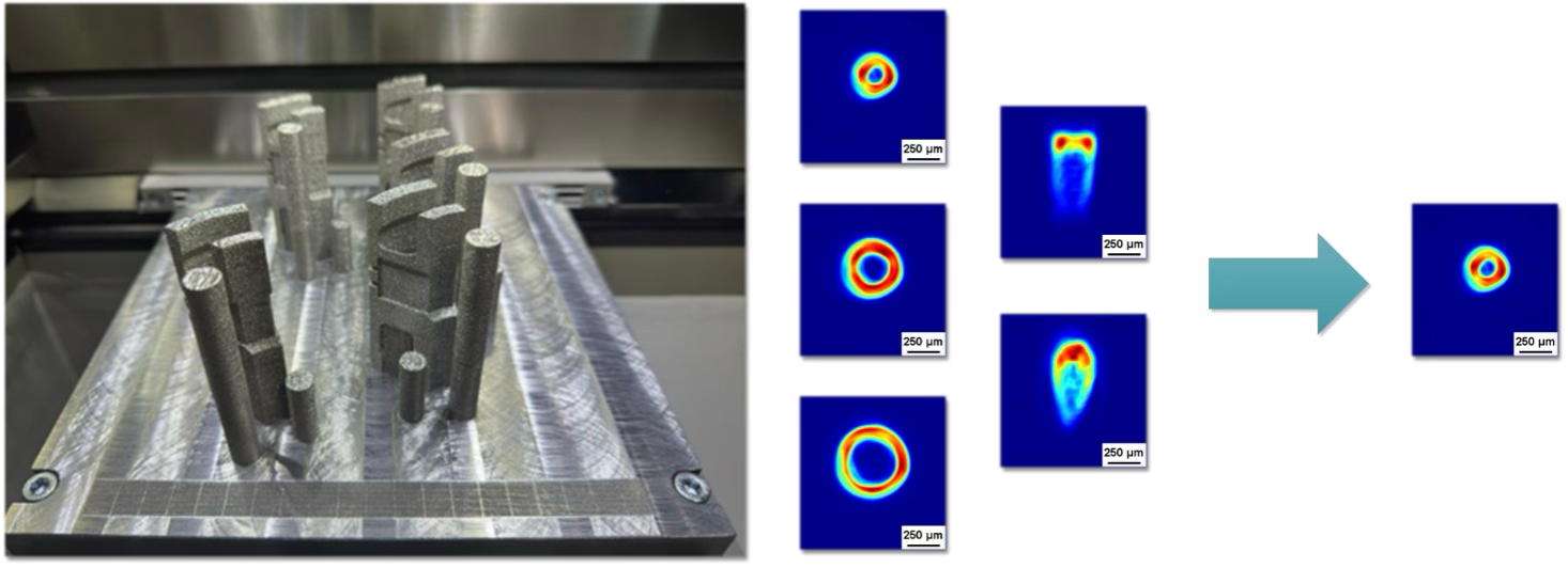
Figure 1 – Image of a build job produced with innovative beam shaping system and differenti beam shapes applied to coupon and sections of the final use case part. Images: BEAMIT
Each iteration was followed by comprehensive analyses, including:
- Density evaluation
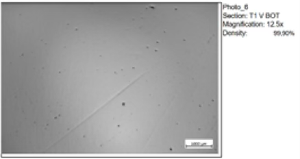
Figure 2 – Relative density image of In718 produced with beam-shaping system Images: BEAMIT
- Metallographic inspections, examining the microstructure at multiple heights (top, mid, bottom) and orientations (horizontal, vertical).
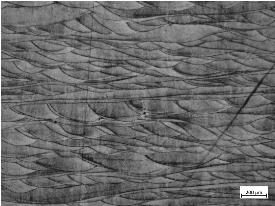
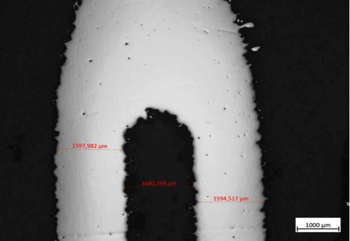
Figure 3 – Metallographic image of In718 produced with beam-shaping system and section of swirler produced with Innovative technology Images: BEAMIT
- Mechanical testing of both horizontal and vertical samples.
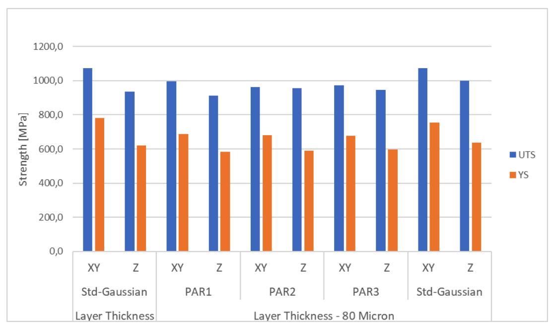
Figure 4 – Final comparison of yield and tensile strength between process parameters developed in InShaPe and state-of-the-art parameters (BEAMIT). Images: BEAMIT
These findings were validated through full-scale component builds, including complete swirler parts, confirming the reliability of the selected beam shaping parameters for complex geometries.
Additional iterations will be necessary to fully qualify the part and its geometry. Research on beam shaping will continue to focus on enhancing part quality and surface finish, with ongoing optimization in the subsequent phases of the research project.
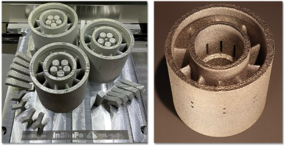
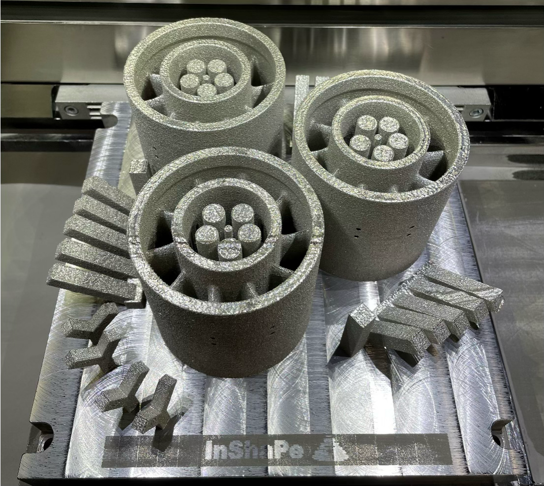
Figure 5 – Build job with three full swirler produced with innovative beam shaping system with optimized process parameters selected as best in term of productivity and material quality. Images: BEAMIT
Thermal Treatments: Strength and Reliability
In parallel, BEAMIT conducted extensive research into advanced post-process heat treatments aimed at enhancing mechanical performance. A comprehensive evaluation was carried out, systematically testing combinations of stress relief, Hot Isostatic Pressing (HIP), solution treatment, and aging. This integrated approach – combining optimized process parameters with precisely tailored heat treatments – paved the way for reliable, high-quality production of complex AM components.
The importance of this research is underscored by the inherent properties of Inconel 718 (IN718), which requires heat treatment to achieve its final metallurgical structure and mechanical performance. Recognizing this, BEAMIT partnered with IMT to carry out an in-depth characterization campaign, with the findings to be published soon in a dedicated research paper. The insights gained from this research are highly valuable, as they establish the optimal heat treatment sequence to achieve superior mechanical properties, while also boosting productivity and reducing lead times by streamlining the entire value chain.
The results could also provide key insights into how heat treatments can be further fine-tuned and optimized specifically for materials produced using beam shaping technology.
A Strategic Vision for the Future
The InShaPe project has proven the potential of beam shaping in additive manufacturing, boosting productivity and process efficiency.
The future of AM lies in innovative approaches like beam shaping, breaking down long-standing barriers and bringing additive manufacturing ever closer to the demands of the most advanced industries.

Gaussian, top hat or donut? Part II: Exploring the effect of beam shape on the productivity and density of additively manufactured AlSi10Mg.
In Part I, we evaluated different laser beam shapes and process parameters with the aim of producing both dense (porosity ≤1%) and high productivity parts in AlSi10Mg with PBF-LB/M. Now, in part II, we reveal the experimental results and performance.
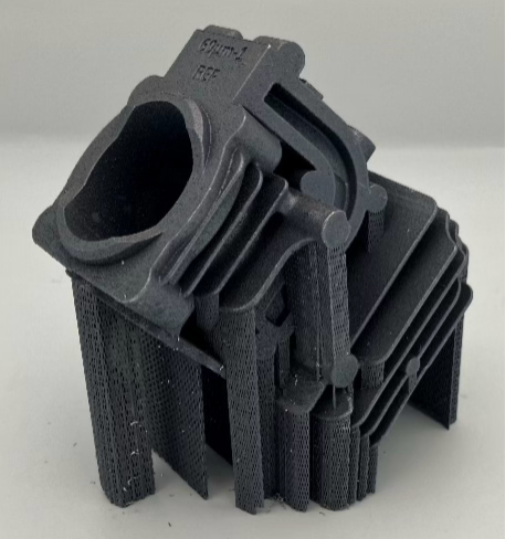
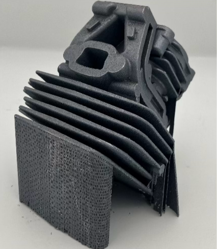
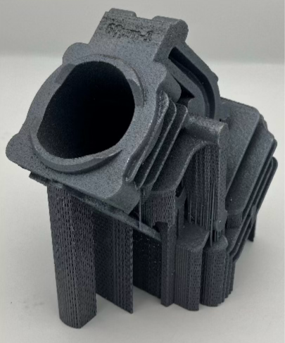
Figure 1. Cylinder head component (use-case 4) produced with 250 µm top-hat beam shape and 60 µm layer thickness.
Images: Stephanie Symons, AMEXCI Materials Lab.
A total of twenty print jobs were produced in M290 using laser technologies of both the InShaPe alpha prototype system and the nLight research platform in EOS Krailling, Germany. The build jobs served various purposes, including process and surface parameter development as well as melt pool dimension evaluation, aiming to produce high density and productivity use-case components (Figure 1), and validation specimens (density cubes, tensile bars), as well as fatigue specimens. Additionally, one reference build job was specifically produced using standard EOS parameters for 60 µm layer thickness (Gaussian beam) to produce benchmarks for use-case components, density cubes, tensile and fatigue specimens. Although 60 µm, 90 µm, and 120 µm layer thicknesses were initially considered for process parameter development within the InShaPe project, due to time constraints, the focus narrowed to 60 µm and 120 µm.
Process parameter development strategies
The results from the initial five designs of experiments (DOEs) showed a good balance between relative density and productivity using 1250W laser power with 250 µm beam spot, where the top hat beam shape had higher relative density on average compared to the donut beam shape at the same build rate (Figure 2).
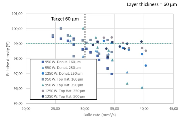
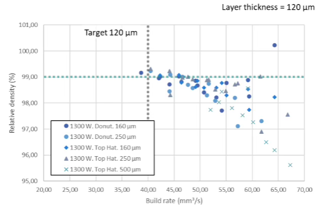
Figure 2. Relative density of cube samples produced using different combinations of beam spot size, hatch distance, laser power, laser speed and beam shapes analyzed using Archimedes density estimation.
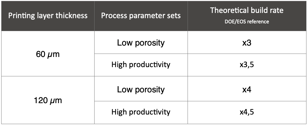
Two additional DOEs (120+ density cubes) were printed for 60 µm and 120 µm layer thicknesses with varying scan speeds and hatch distances focused around the process parameters of cubes with the most promising relative density from the initial DOEs. In the end, two process parameter sets were selected for both 60 µm and 120 µm layer thicknesses: the first (low porosity) which focused on our goal of minimizing porosity while maintaining productivity and a second (high productivity) to further push the build rate (Table 1).
Table 1. Increased productivity of parameter sets developed by InShaPe when compared to standard printing parameters by EOS (AlSi10Mg with M290).
Density of cubes and cylinder heads
The cubes were sectioned into three areas by using a longitudinal cut followed by a transversal cut as shown in Figure 3 (left). Meanwhile, the cylinder head components were sectioned to evaluate at least three areas, near the cylinder walls or the cooling fins, as shown in Figure 3 (right).
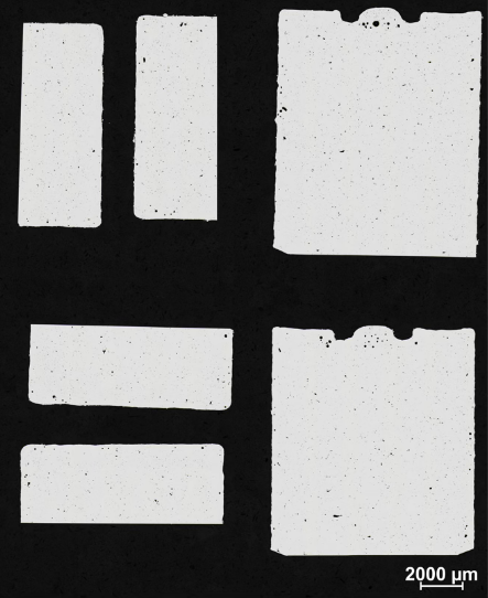
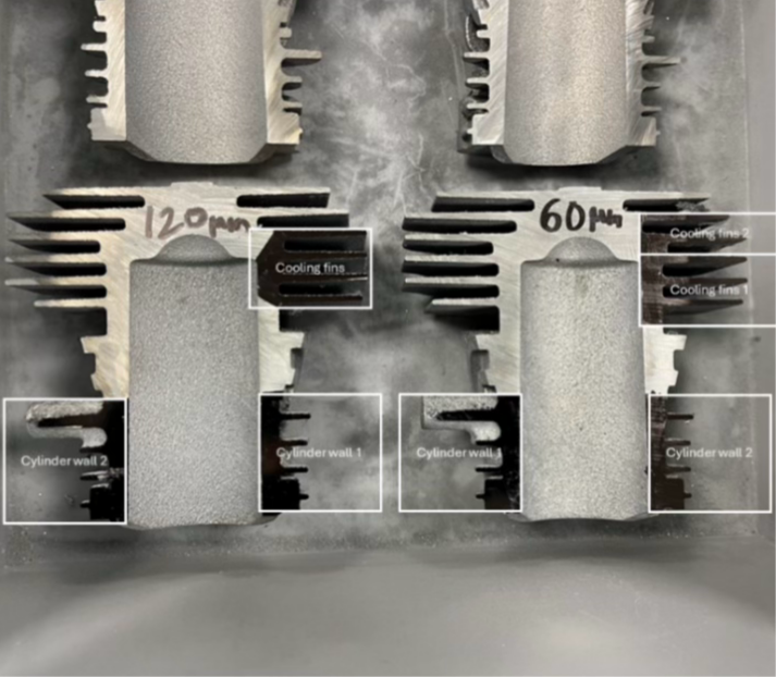
Figure 3. Example of sections used for the porosity evaluation in (left) two cubes and (right) cylinder head components. Images: Stephanie Symons, AMEXCI Materials Lab
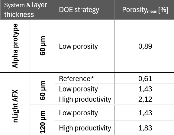
DOEs targeting high productivity tended to show increased porosity compared to those optimized for high density. As shown in the Table 2, porosity percentage of cubes varied depending on the process parameter sets’ strategy and which beam shaping technology was used where the Alpha prototype systems generally had higher densities than nLight AFX under similar conditions, particularly when printing with 60 µm layer thickness. Unfortunately, the Alpha prototype system became unstable during printing, therefore all cylinder heads except for one were printed using the nLight AFX. Due to time constraints within the project, further exploration using the Alpha prototype was not feasible; however, it presents an interesting opportunity for future work beyond the scope of this study.
Table 2. Summary of cube porosities [%] measured by contrast-based analysis using light optical microscopy (Nikon LV150N) and NIS-Elements BR software.
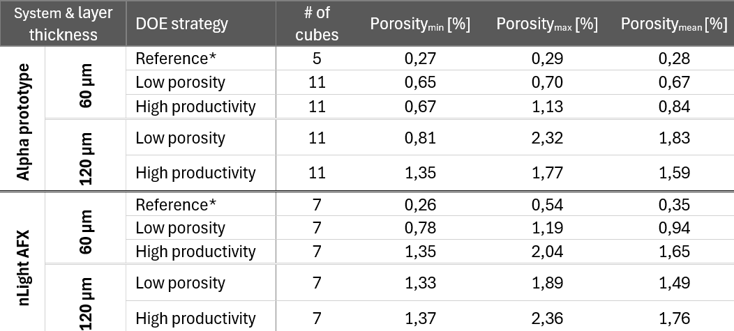
*The reference cubes were printed in the EOS M290 fitted with the alpha prototype system or nLight AFX with beam shaping turned off, using Gaussian.
As expected, in comparison to density cubes, porosity increased when larger, more complex cylinder head parts were printed (Table 3), where higher porosity was observed in cross sections near the cooling fins.
Table 3. Mean cylinder head porosities [%], printed with 60 µm and 120 µm layer thickness, measured by contrast-based analysis using light optical microscopy (Nikon LV150N) and NIS-Elements BR software.
*The reference cylinder head was printed in the EOS M290 fitted with nLight AFX with
beam shaping turned off, using Gaussian.
The data reveal a clear trade-off between productivity and part quality when using newly developed low porosity and high productivity parameter sets with beam shaping technology. While both parameter sets lead to increased porosity (especially when applied to complex geometries like cylinder heads) they also offer a significant increase in theoretical build rate compared to the standard EOS reference parameters as indicated in Table 1. These results highlight a critical balance: while faster parameters can dramatically improve manufacturing throughput, they may not yet provide sufficient quality for AlSi10Mg applications where high density is essential.
Mechanical Properties
Tensile properties
Initially, two print jobs with varying process parameters were manufactured to obtain a preliminary evaluation of the mechanical properties of samples. The preliminary results showed that process parameters closest to the selected DOE strategies (based on density) met the key performance indicators, confirming the validity of our process parameter selection. Next, for each set of the selected process parameters, 10 tensile samples were printed alongside the cylinder heads using the nLight AFX system at 60 µm (reference, low porosity, and high productivity parameters) and 120 µm (low porosity and high productivity parameters). Here it is relevant to highlight that 240 MPa ultimate tensile strength and 70 GPa Young’s modulus were used as key performance indicators (KPIs) for AMEXCI’s use-case application within the InShaPe project.
Tensile specimens produced with high productivity parameters in both 60 and 120 µm layer thicknesses achieved average Young’s moduli of 68 ± 3 GPa and 69 ± 1 GPa, respectively, which is just below the target KPI of 70 GPa (Figure 4). Similar results were observed for ultimate tensile strength where high productivity parameters also fell slightly short of the 240 MPa target KPI (60 µm: 223 ± 35 MPa and 120 µm: 224 ± 17 MPa; Figure 5). On the other hand, the low porosity parameters successfully reached both targets showing that beam shaping can increase in productivity of x3 for 60 µm layer thickness and x4 for 120 µm layer thickness compared to standard printing parameters. Other mechanical properties, such as yield strength (Figure 6) and elongation after fracture (Figure 7) are also presented, although no reference requirements were established for these properties.
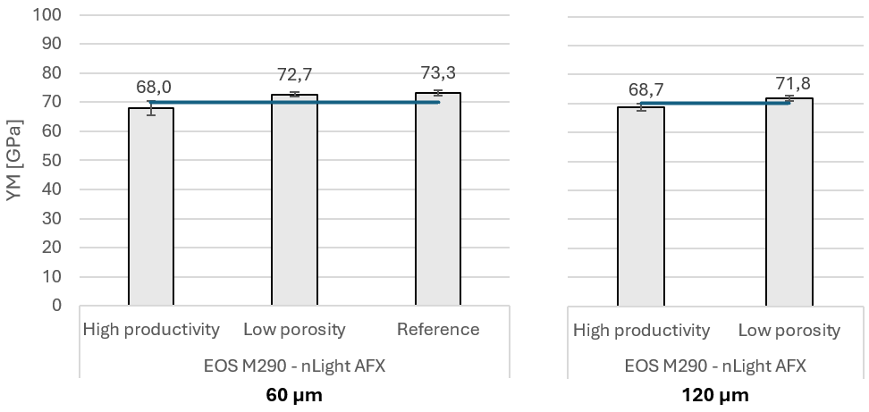
Figure 4. Average Young’s modulus (YM) of samples printed with 60 and 120 µm layer thickness. The high productivity and low porosity process parameter sets were developed by the InShaPe project, where the reference process parameters are the standard process parameters for 60 µm layer thickness. The blue line at 70 GPa shows the key performance indicator for this mechanical property. Error bars around the mean represent one standard deviation.
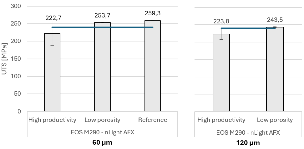
Figure 5. Average ultimate tensile strength (UTS) of samples printed with 60 and 120 µm layer thickness. The high productivity and low porosity process parameter sets were developed by the InShaPe project, where the reference process parameters are the standard process parameters for 60 µm layer thickness. The blue line at 240 MPa shows the key performance indicator for this mechanical property. Error bars around the mean represent one standard deviation.
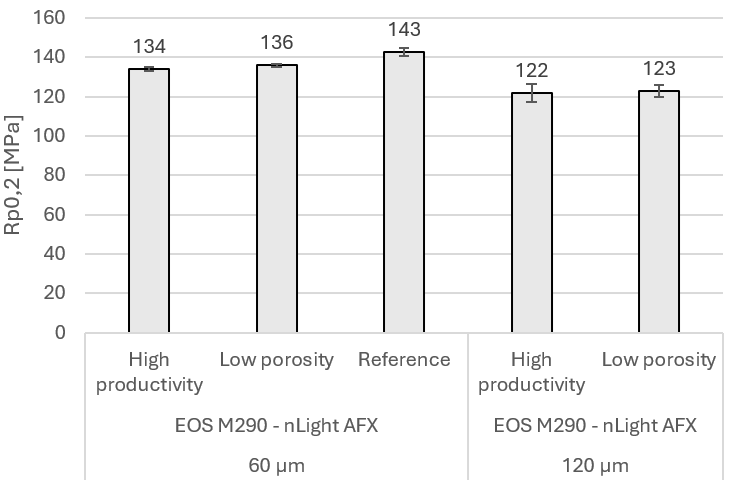
Figure 6. Average yield strength (Rp0,2) of samples printed with 60 and 120 µm layer thickness. The high productivity and low porosity process parameter sets were developed by the InShaPe project, where the reference process parameters are the standard process parameters for 60 µm layer thickness. Error bars around the mean represent one standard deviation.
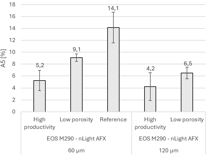
Figure 7. Average elongation after fracture (%) of samples printed with 60 and 120 µm layer thickness. The high productivity and low porosity process parameter sets were developed by the InShaPe project, where the reference process parameters are the standard process parameters for 60 µm layer thickness. Error bars around the mean represent one standard deviation.
Fatigue properties
Fatigue testing was conducted at the Institute of Metals and Technology (IMT), Slovenia, using a StepLab Electrodynamic testing machine UD020 machine at high temperature (240°C) where the loading was imposed only in tension (R=0.1). Seventeen and eighteen specimens were used to establish S/N curves with printing parameters according to EOS standard for M290 (hereafter, reference) and 60 µm-low-porosity parameters (hereafter, beam shaping) developed by InShaPe, respectively. All fatigue specimens were printed in the vertical direction and stress relieved at 300°C for 2 hrs. Before testing, specimens were machined and polished to reduce surface roughness.
For the case component under consideration, the material should sustain 5×10⁶ cycles when a maximum stress of approximately 100 MPa is applied at 250 °C. Due to limitations within the testing equipment, samples were only able to reach 240 °C. In Figure 8, it can be observed that the fatigue performance of samples printed with beam shaping was lower than the reference samples. Fatigue life with 50% certainty was 73 MPa for beam shaping specimens and 86 MPa for reference specimens.
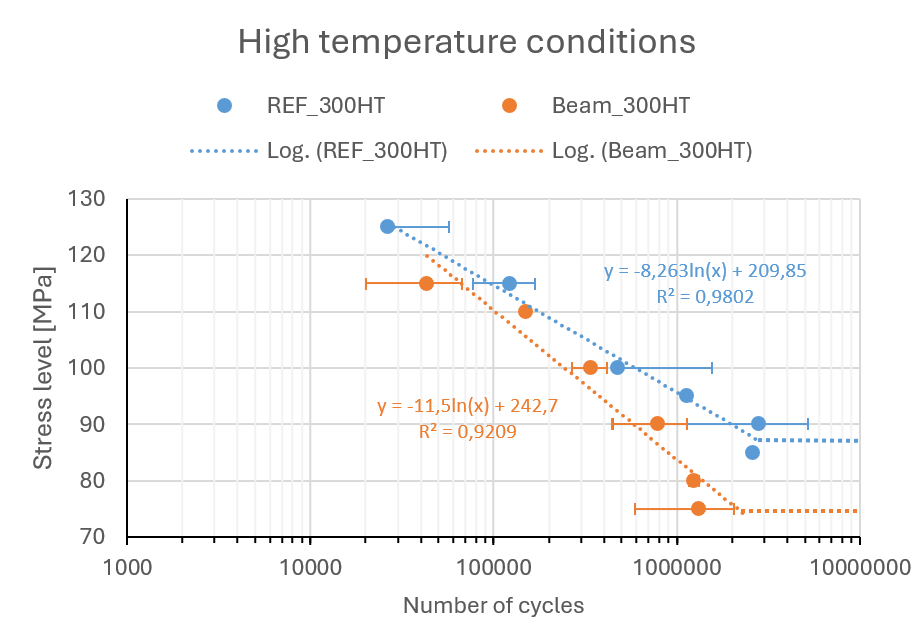
Figure 8. S/N curves for the specimens tested at high temperature (240 °C) printed with EOS standard parameters (blue) and InShaPe low porosity beam shaping parameters (orange).
The lower fatigue life observed with beam shaping is likely a result of increased porosity within the samples. As we observed a 2-fold increase in the porosity of cylinder heads (Table 3) printed with the low-porosity beam shaping parameters compared to the reference parameters, this could lead to faster crack initiation.
Other challenges
- Porosity vs. Productivity: the 250 µm top-hat parameters result in higher porosity than commercial systems. This indicates a trade-off between productivity and material quality. Further optimization of parameters such as scan speed, power, hatch distance is needed but is beyond the scope of the remaining InShaPe project timeline.
- Parameter Transferability: Two systems were used for the density determination of cubes and a comparison of one cylinder head. Differences in densities across DOEs may stem from parameter instability, system differences, or limited parameter transferability. Due to time constraints, we were unable to further compare the two beam shaping systems.
Date: 27-05-2025

Open Innovation Service Winner
As part of our Horizon Europe project InShaPe, we are excited to announce the winner of our Open Innovation Service (OIS). The initiative was developed to invite innovators from all industries to shape the future of manufacturing with the goal to advance Additive Manufacturing beyond traditional manufacturing methods. We seek to expand industrial use cases leveraging our expertise and cutting-edge technology.
The winning submission to the OIS is from Airbus Defence and Space with an application linked to Space communication hardware.
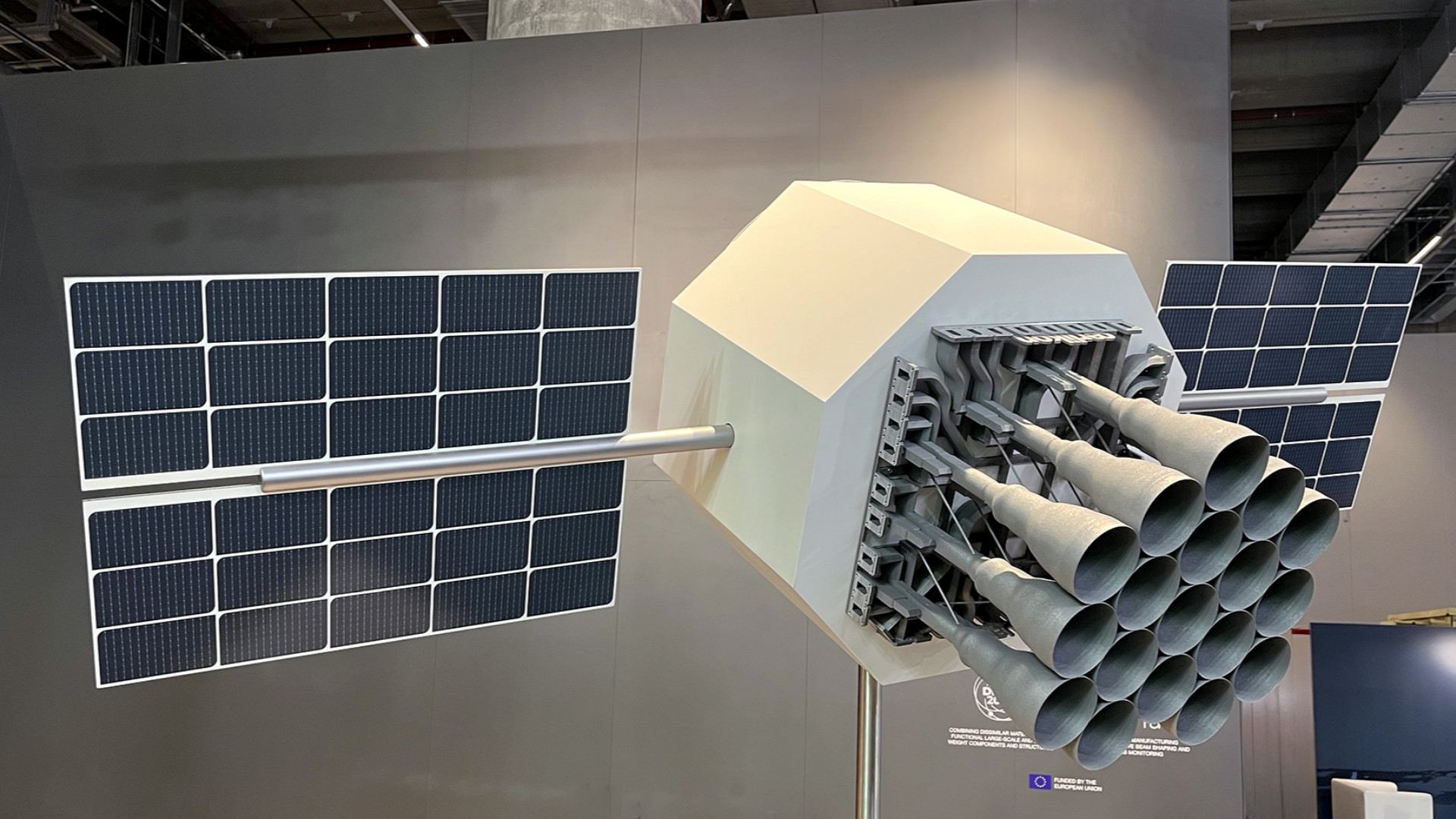
Figure 1 Ready for space – and ready for industrialized AM production: The 3D-printed aluminium antenna cluster for next-generation communication satellites, made to orbit the earth.
Picture Credits: Oerlikon
Airbus has already introduced additively manufactured components using laser-based powder bed fusion of metals for space communication hardware in serial production. The InShaPe laser beam shaping technology could further enhance this hardware in terms of productivity and quality, which is why Airbus is interested to explore this together with the InShaPe consortium. This use case aligns perfectly with the goals of the OIS, aiming to shape the future within the industry and explore novel metal applications to create significant impact. In a future blog, we will dive deeper into the potential benefits of laser beam shaping for this use case.
Three other submission finalists were considered for the OIS. The use case from Airbus was not the only space-related submission we received. Another innovative idea was for a monolithic spacecraft thruster designed for Water Electrolysis Propulsion (WEP) systems, utilizing hydrogen and oxygen as propellants. Using AM and laser beam shaping could enhance cooling, allowing for a material change that significantly improves the economics of manufacturing with AM.
Cooling or heat transfer was also a theme in use case submissions beyond space applications. Utilizing beam shaping to create controlled porous or lattice structures, forming closed foam-like areas within a component, can be beneficial across various industries. This approach can reduce heat transfer or achieve lightweighting while maintaining clean, functional surfaces for applications like fluid flow.
Controlling stiffness to mimic natural elasticity and promote optimal bone ingrowth makes lattice structures interesting for medical applications, which was another idea of one finalist. The delicate nature of these applications, with very small minimum feature sizes and intricate structures, could benefit from laser beam shaping technology and novel in-situ monitoring processes.
This Open Innovation Service offered a platform to showcase real industrial parts and explore the benefits of innovative beam shaping for Additive Manufacturing, including precision, quality, cost-efficiency, and sustainability.

With its laser beam monitoring system using multispectral sensors, the EU-project InShaPe is at the forefront of multispectral imaging worldwide
The image rights are held by SILIOS Technologies
SILIOS Technologies takes profit of the developments made during the EU project InShaPe on Laser-Based Additive Manufacturing domain to keep its advance in multispectral sensors against worldwide competition, extend its Multispectral cameras and sensors portfolio and adapt them in order to address other markets.
The two innovation pillars of InShaPe project innovation are combined Flexible adaptation of laser beam shapes with AI-techniques to determine the optimal beam shapes for the target value (e.g., determined by material type) and a Multispectral in-line process monitoring & control system for predictive quality analysis.
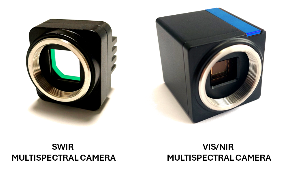
Within EU InShaPe project, the target of SILIOS Technologies is to enable the transfer of the multispectral imaging technology to the Laser-Based additive manufacturing domain in collaboration with the other leading Research Institutions and Industrial Partners that constitute this unrivalled consortium. Then, as exploitation tasks, SILIOS Technologies is willing firstly to offer a solution for the specific powder bed-based additive manufacturing of metals application with the developed VIS/NIR and SWIR Multispectral cameras and proposes its solutions at several exhibitions on demanding domains such as Space for instance. Secondly SILIOS Technologies is currently benchmarking these multispectral sensors in order to define what is to be adapted in terms of spectral bands, spectral resolution, spatial resolution to approach other markets and provide new solutions for them.
About the VIS/NIR cameras specifically made for PBF-LB/M process within EU InShaPe project, we found as target applications whatever processes using tooling Lasers, not only Laser-Based additive manufacturing, but also on metallurgy, nuclear applications for instance where they image molten metal surfaces and look at temperature and emissivity.
Concerning the SWIR cameras, we succeeded during EU InShaPe project in developing an unrivalled Snapshot Synchronous Bayer type SWIR Multispectral camera. Now it has been manufactured in the fall of 2023 to be supplied for implementation in the PBF-LB/M machine at TUM, it was the only SWIR multispectral camera of this type available on the worldwide market. It was proposing a 1.3 Mpix spatial resolution and with 5µm pixel size offering a very low footprint making it easy to integrate in production lines or machines.
Ahead in this technological advance, SILIOS Technologies is looking at other markets and a strong interest has appeared in Defense (Decamouflage, Laser Alert detection applications), Space (Space Domain Awareness, Planet exploration on Rovers applications), Quality control and defect detections in production lines where humidity has to be detected and monitored, Plastic sorting machines (due to last EU rules where a distinction has to be made among the different PETs (not only the different plastics as previously) and others. The high interest in these SWIR multispectral cameras is linked to their extreme versatility (thanks to a capability of spectral bands selections) and to their extremely small footprint and weight, allowing them to be placed on military vehicles, drones, soldiers, SmallSats, production and sorting machines etc.
To conclude, with the EU InShaPe project, SILIOS Technologies worked to remain at the cutting edge of multispectral sensor technology and to strengthen its leadership position in many markets. It reinforces SILIOS as a European player in the worldwide Multispectral Imaging competition.
Authors : Thierry Berthou, Vincent Sauget, Stéphane Tisserand

Leveraging the Benefits of Laser Beam Shaping on a Demonstrator Application
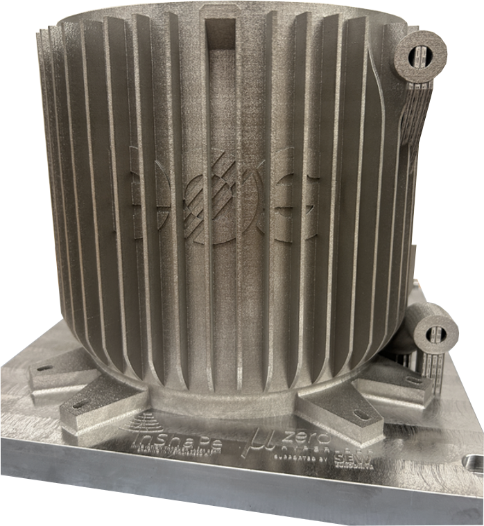
The technology developed within the EU project InShaPe enables new, application-optimized processing strategies for the additive manufacturing process Laser-based Powder Bed Fusion of metals (PBF-LB/M). These optimized strategies lead to significant benefits in key performance indicators such as productivity, energy consumption, material usage, and manufacturing costs. This is demonstrated in the following sections through an application demonstrator build job of a heat exchanger. The part geometry was kindly provided by “mu-zero | Hyperloop”. In addition to the heat exchanger, text and “feather” geometries are added to test detail resolution. The whole job layout is shown in Figure 1.
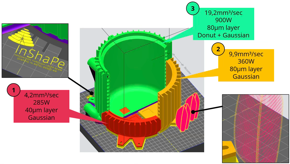
Figure 1: Job layout of the application demonstrator with parameter assignments.
Job setup
The material used is IN718. The primarily rotationally symmetric application geometry is divided into three segments, each assigned a different process parameter, as described in Table 1, allowing for direct visual comparison of the manufactured parts. The respective build heights of the segments reflect the nominal productivity of each parameter used: in a 30-hour build time, parameter 1 completes 25% of the part, parameter 2 completes 60%, and parameter 3 completes the entire part.
For parameter (3), a combination of a donut and Gaussian beam shape is used. The donut shape, with specific parameter properties, is employed for the bulk infill, while the Gaussian shape is used only for the part’s contour.
The job was built on an InShaPe EOS prototype system with a single laser, which allows for fast switching of the beam shape during the process. The build plate measures 250 x 250 mm2, and the job is 180 mm in height.
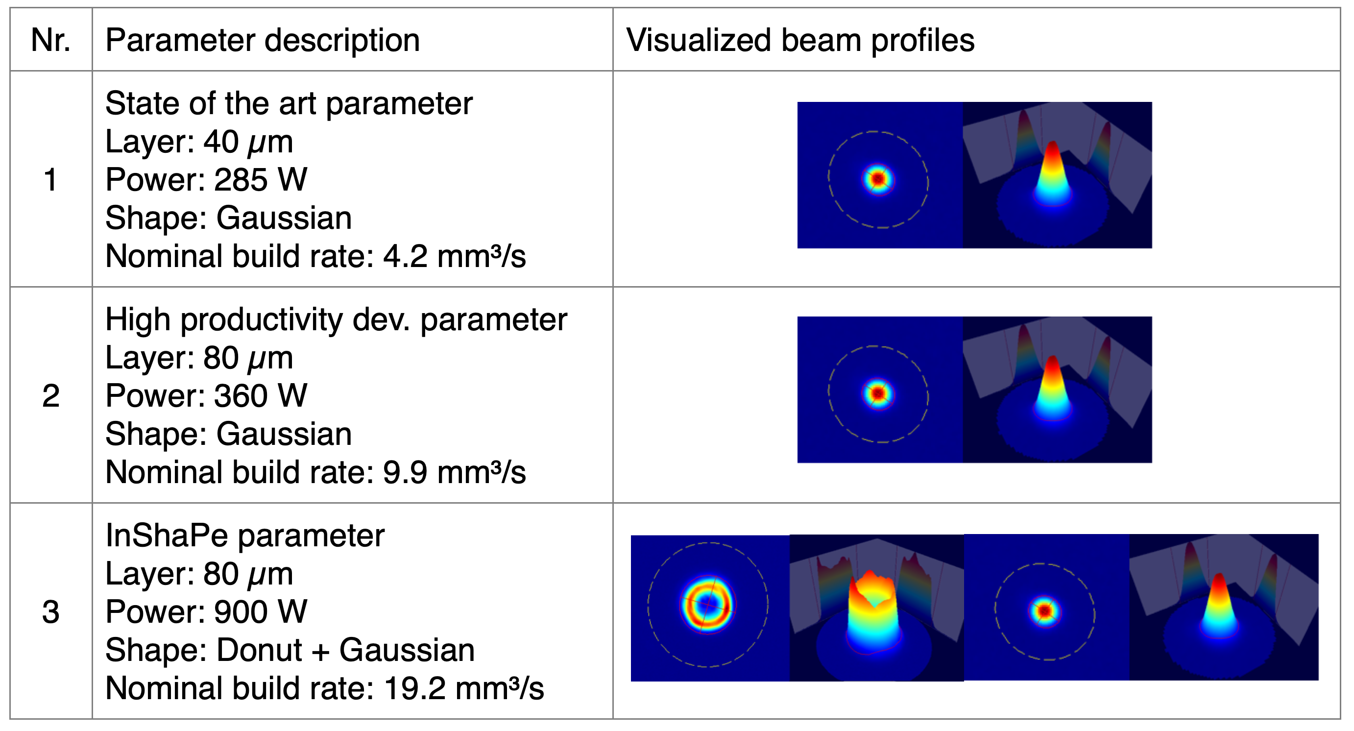
Table 1: Used process parameters
Manufacturing Process
As two different layer thicknesses, 40 µm and 80 µm, were combined in a single job, recoating occurred in 40 µm steps, with exposure of the 80 µm parameters performed only every second layer. Despite the high power, productivity, and large exposure areas, recoating was very smooth, even at a 40 µm layer thickness—typically an indicator of a stable, high-quality PBF-LB/M process. Figure 2 shows a powder bed image after exposure and after recoating, with a consistently applied powder layer.
Visible in Figure 2 (indicated by the green and orange circles), the productive InShaPe parameter (3) appears to produce fewer spatters than parameters (2) and (1) as can be seen by fewer “black dots” in the image. Spatters created by the laser-material interaction are typically ejected from the process zone, carried by the gas flow, and either fall back onto the powder bed downstream or are transported to the filtration system. For parameter (3), less material appears to be ejected, or the spatter morphology is more efficiently managed by the gas flow.
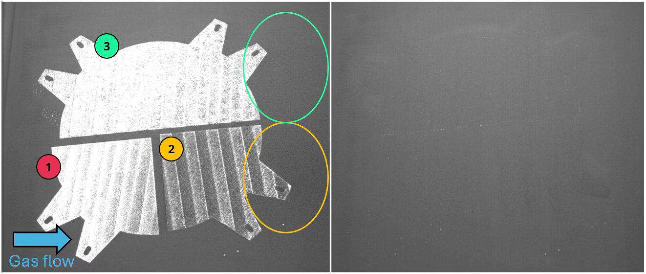
Figure 2: Powder bed image after exposure (left) and after recoating (right) early in the build job. The numbers indicate the assigned parameters.
Evaluation
The completed build job, shown in Figure 3, displays no obvious defects or visible differences between the three parameters.
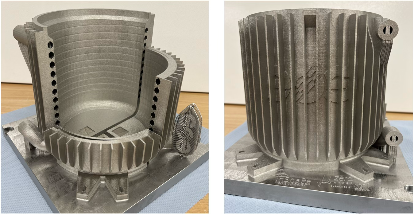
Figure 3: The manufactured parts shown from two sides
Figure 4 details the fine detail text, “feather” parts, and upskins of the three parameters. The fine detail parts were manufactured with a Gaussian beam, as they mainly consist of wall thicknesses down to 100 µm, requiring the highest resolution possible. All details were built successfully.
In the three upskin segments, rectangular “windows” into the part reveal areas where no upskin was applied, showing the “raw infill.” As observed, the InShaPe parameter (3) with its donut beam shape appears significantly rougher than the other parameters with a Gaussian beam. Focusing on the upskin, it is evident that a suitable combination of exposure strategies can mask the rougher appearing inskin, achieving an identical surface finish to that of the other 80 µm layer thickness parameter (2).
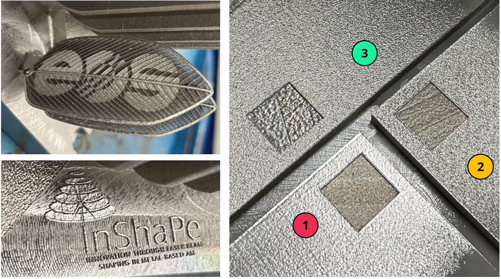
Figure 4: Fine detail geometries (left) and upskin regions (right)
Figure 5 shows a side- and downskin comparison of the build job. Here, the InShaPe parameter (3) produces the most shiny and homogeneous surface among all parameters. Interestingly, the detail of the cooling channels shows excellent geometric accuracy, even compared to the 40 µm layer thickness parameter (1). For parameter (3), the vertical walls are truly vertical, and the downskin regions are smooth and even, as intended.
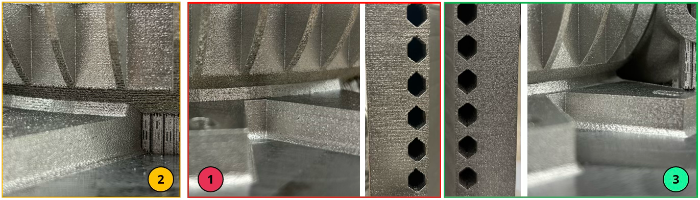
Figure 5: Images of the side- and downskin regions and detailed image of the cooling channels.
Conclusion & Outlook
This demonstrator build job shows that beam shaping and the flexible use of various beam shapes allow for significant advantages:
- Compared to the current state-of-the-art parameter, a nominal build rate increase of approximately 4.6 times was achieved.
- Despite the higher layer thickness and the larger donut beam shape, there is no loss in geometric accuracy; instead, geometric accuracy even appears improved.
- Surface finish for the downskin was best with the InShaPe parameter and mostly unchanged for side- and upskins. The InShaPe parameter generally showed the most homogeneous surface morphology.
- Despite high laser power and build rate, the InShaPe parameter seems to emit fewer spatters than the Gaussian counterparts.
- Small features can be built effectively by switching to the Gaussian beam shape.
As this test primarily focused on the visual comparison of the three parameters, future investigations will also examine the material properties achieved. The analysis of spatter emissions is crucial for reducing material waste and improving the economic footprint of additive manufacturing.
Overall, the current results already look very promising and provide a solid foundation for further benchmarking the application demonstrator against the InShaPe KPIs of productivity, energy consumption, material usage, and manufacturing costs.
Authors: Markus Birg, Fabian Sonnen | EOS
All images: EOS

Demonstrating the potential impact of project InShaPe with Additive Manufacturing use cases, Part 1

To demonstrate the impact of the technology developed in the EU project InShaPe, we have four relevant use cases: An impeller, a chainsaw cylinder head, an industrial gas turbine swirler and a primary combustion chamber for rocket engines. Parts such as these are already being manufactured using conventional Laser Powder Bed Fusion (LPBF) but there are significant opportunities by introducing state-of-the-art LPBF with beam shaping.
The four use cases cover 3 different alloy families commonly used in LPBF: Ni-based super alloys, Cu-based and Al-based alloys. For each of the use cases we aim to demonstrate the goals of the project.
InShaPe is aiming for:
-
a seven times higher production rate
-
over 50 % lower costs
-
60 % less energy consumption
-
30 % less waste
Cost of parts produced by AM is still one of the biggest barriers we have to overcome in order to enable more products to unlock their AM potential. Although the technical developments are centered on printing and utilizing beam shaping, the impact on the products affects the whole value chain from selecting materials and designing parts to the required post-processing and how parts or materials are qualified. As an example, if the printing process is more robust and produces less defects, this not only means potentially scrapping fewer parts and allowing for less effort in qualification and quality control.
Impeller
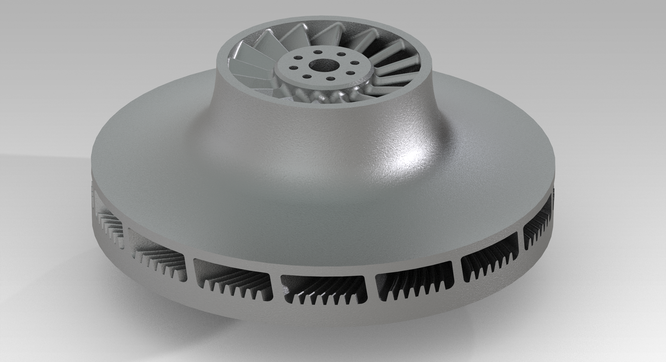
Figure 1. Impeller Image: Oerlikon AM
For the impeller we have a complex geometry with internal channels, which are not easily accessible, or in line of sight for post-processing. This poses a critical challenge in printing and achieving a good surface finish. Overhang and down-skin surfaces need to be smooth for best performance of the impeller. The current surface finish requirements are limiting the design freedom of the impeller with the conventional LPBF processing. Another key aspect is managing the residual stresses, which requires a lot of support structure and stock material. Printing this extra material not only increases the print time but also must be removed after the printing. This generates scrap and consumes energy resulting in a higher manufacturing cost.
Engine Cylinder Head
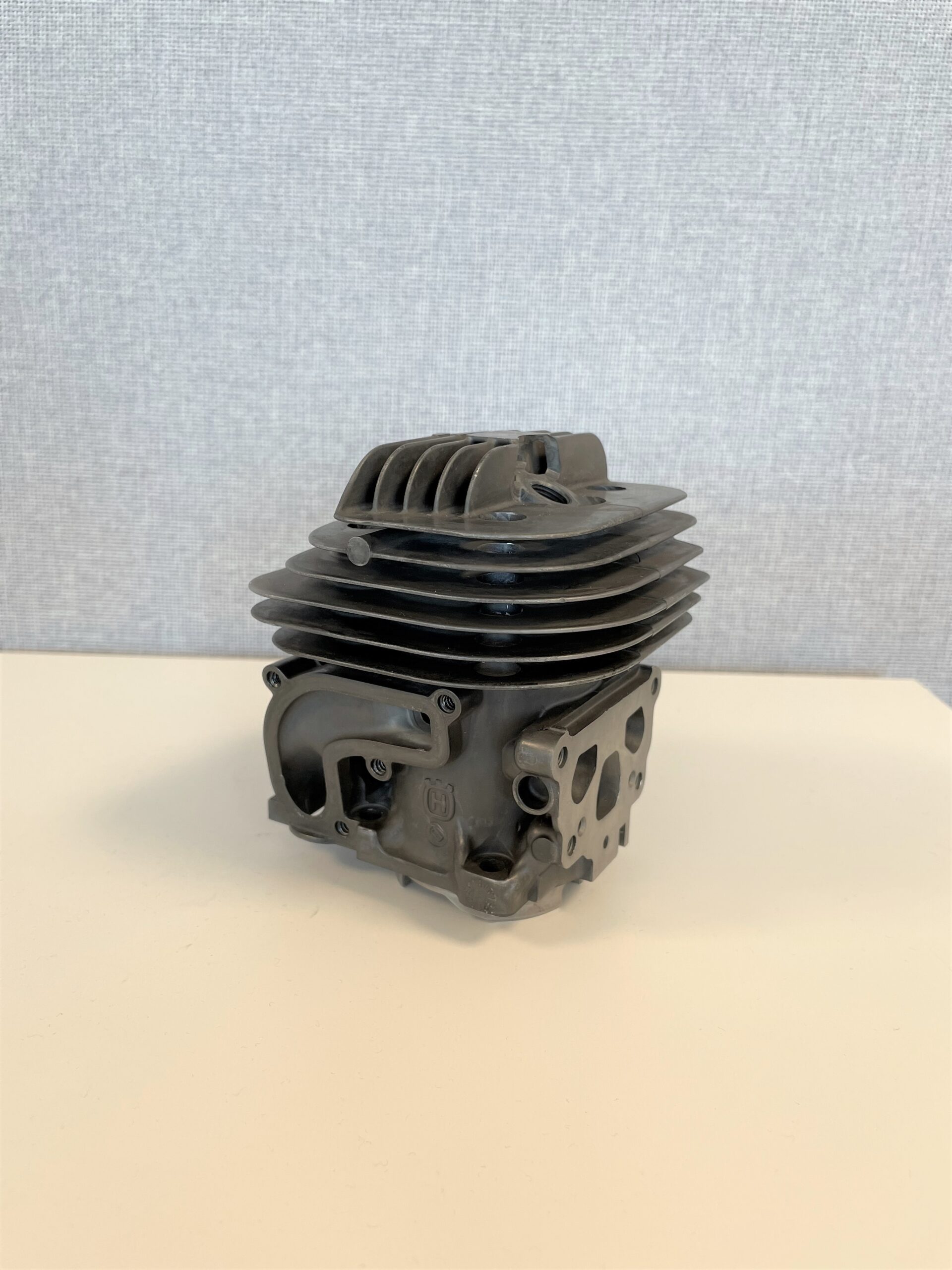
Figure 2. Engine cylinder head for a hand-held chainsaw Image: AMEXCI
Additive manufacturing (AM) is a suitable production method for cylinder heads with complex design. Furthermore, in this specific application, where the component is used in a handheld chainsaw, AM provides extraordinary potential for weight reduction, better user experience and overall improved performance. Nonetheless, to fully exploit the potential of laser powder-bed fusion (LPBF) for weight reduction, lower manufacturing costs, and higher production rates and volumes are necessary, as required production volumes for this part assent to up to 100.000 units per year. Here, the InShaPe technology could enable significant improvements and expand the use of AM to new use- and business-cases.
Industrial Gas Turbine Swirler
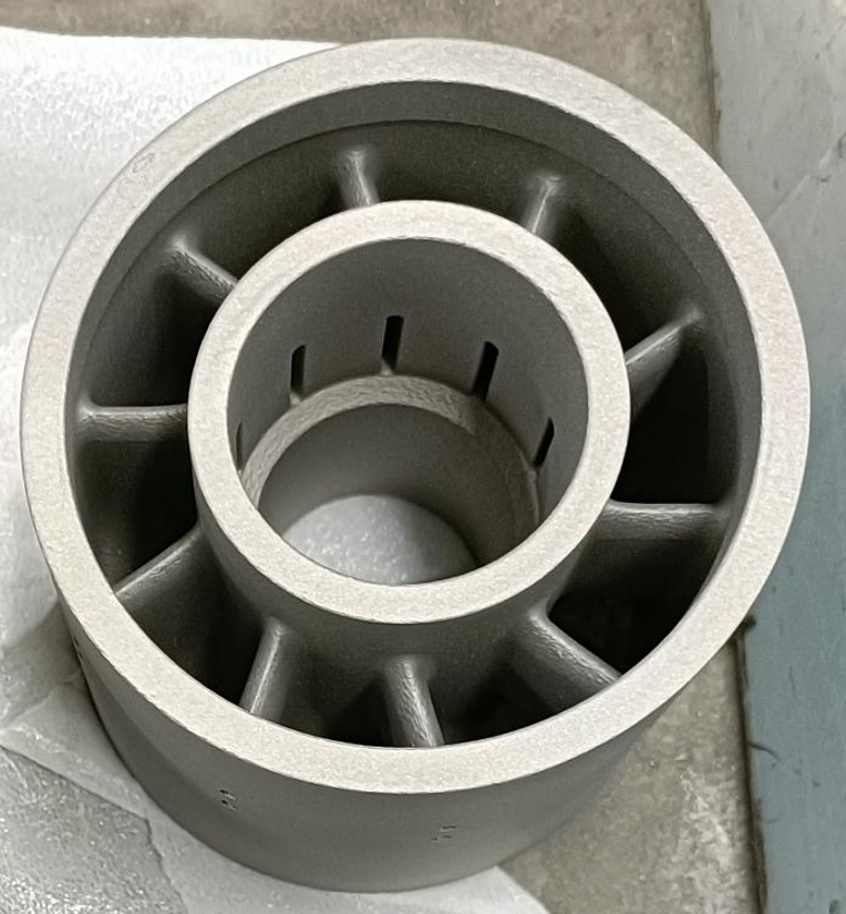
Figure 3. Industrial Gas Turbine Swirler Image: Federico Uriati/BEAMIT
A swirler in industrial gas turbines (IGT) enhances fuel-air mixing and combustion efficiency while reducing emissions. Constructed from high-temperature materials and designed in various configurations, it improves operational flexibility. Laser Powder Bed Fusion (LPBF) further refines swirler design by enabling complex geometries and optimized vane shapes, boosting thermal performance and durability. These advancements lead to more efficient, reliable, and emission-reducing swirlers, benefiting power generation and industrial applications
Beamit’s focus in the InShaPe project is on enhancing productivity and achieving specific mechanical properties in the IGT sector. Using IN718, the goal is to increase build rates and maintain continuous machine availability for high productivity and profitability.
Reducing print time is another strategy to cut the manufacturing costs of additive manufacturing (AM) parts. However, increasing productivity in high-performance applications like IGTs must not compromise material properties or printer reliability. This is especially challenging with difficult-to-print materials where only specific microstructures yield crack-free parts. Beyond modifying printers to create shaped beams, the project will explore build file optimization and monitoring to ensure optimal material and process performance. This is crucial as beam shaping introduces additional complexity.
By tackling these challenges, the InShaPe system promises significant reductions in energy consumption, powder use, and engineering hours. This translates to lower production costs, making LPBF-manufactured parts competitive with traditional manufacturing methods.
Combustion Chamber
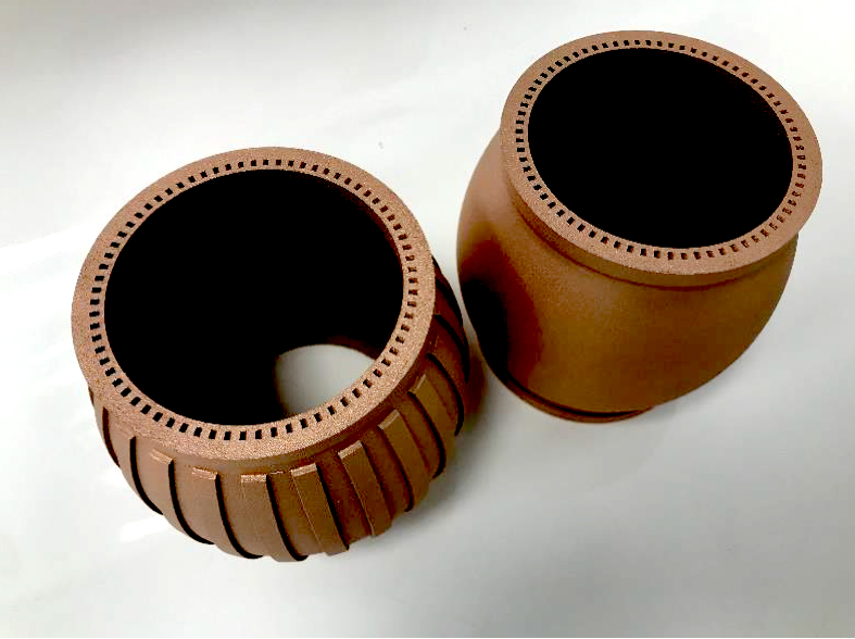
Figure 4. Combustion chamber Image: AENIUM
Exposed to temperatures up to 3500 degrees Kelvin, combustion chambers for first-stage thrusters need the right microstructure to balance the performance required of the Cu alloy, which is only processable with AM. These extreme Cu alloys, such as CuCrNb (NASA GRCop42), require precise cooling rates and stable energy density values throughout the printing areas and volume, ensuring temperature control of the melt pool. Due to the high energy required to process the material with lasers, the process is hard to control while consuming a lot of gas and energy, and it is characterized by very low manufacturing efficiency due to the emissivity and thermal conductivity of the alloy during the printing process. The risk of defects and resulting microstructure means the parts need to go through intensive HIP processing after printing.
AENIUM’s main targets are focused on defining new beam parameters and shapes that ensure increased productivity and stable melt pools without spatter, allowing for increased productivity by ensuring the right microstructure and precipitated elements, resulting in stable and homogeneous grain sizes and microstructure properties with the CuCrNb alloy.
By using InShaPe technology, it is demonstrated during the project that this technology is a game changer for achieving high manufacturing efficiency, production ratios, and stable microstructures when compared with standard YLR lasers and the same LPBF processes. By varying from a Gaussian energy profile in the melt pool to a variable crown controlled by an AI beam shape engine, preliminary tests on the material show productivity increases of up to 4.5X and a reduction in intermetallic and microstructure porosity in the Cu alloys, achieving stable grain sizes and outstanding precipitated element growth throughout the melted areas of the part.
By the end of the project, AENIUM aims to achieve up to a 6-7X productivity increase, 99.95% precipitated element regrowth compared with the standard process, and microcracking-free structures in the application of rocket engine chambers for civil use purposes in additive manufacturing for the space sector.
Beam shaping technology and the InShaPe project offers solutions that could be a game changer, not only for these 4 use cases, and therefore we had an open innovation call where interested parties were invited to submit use cases to be investigated with the solutions developed in the project InShaPe. The fifth use case selected from the open innovation service will be presented in the near future.

Metal Additive Manufacturing adoption of Innovative Beam Shaping Technology for Greater Efficiency and Sustainability. Beamit preliminary test in Garching for Industrial Application.
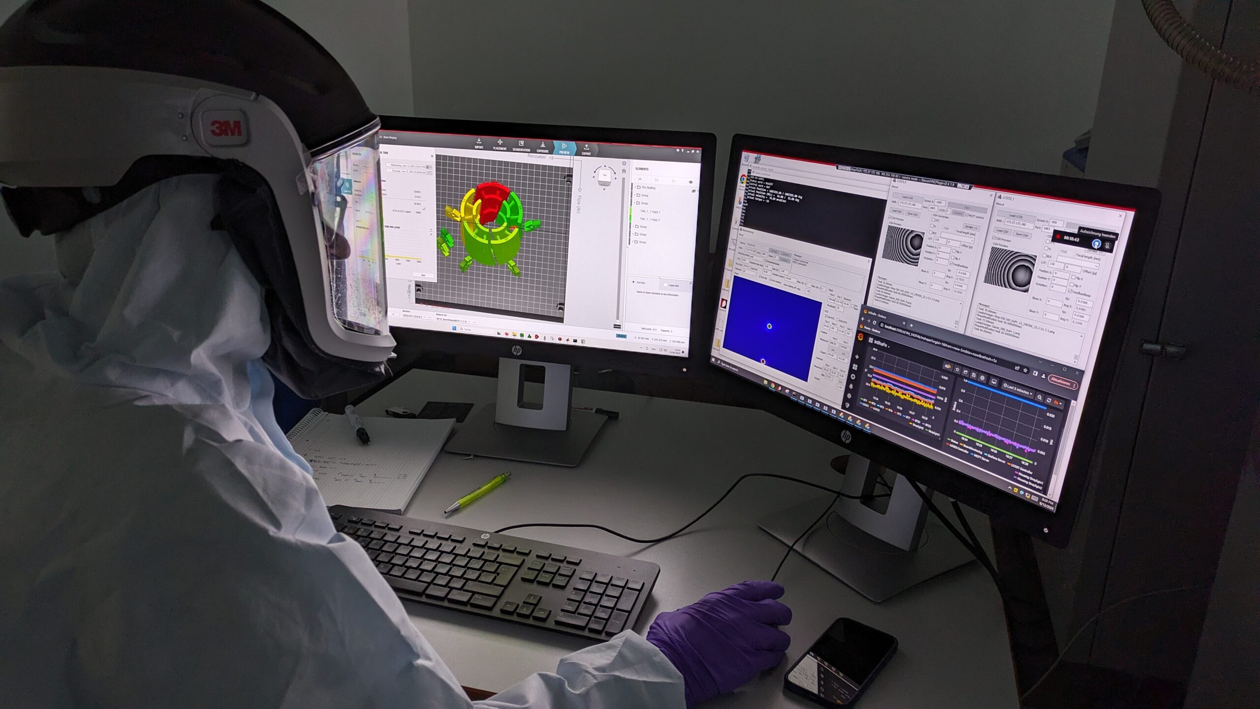
Figure 1. OERLIKON/TUM build job preparation and selection and process parameters and beam shape Images: Federico Uriati/BEAMIT
Authors: Federico Uriati (Beamit), Michele Caldarini (Beamit), Robin Prudlik (Oerlikon)
InShaPe, a groundbreaking project funded by the European Union’s Horizon Europe program, aims to revolutionize metal additive manufacturing by making it faster, cheaper, and more sustainable. The project brings together a consortium of leading research institutions and industrial partners, including Beamit.
Recently, the Beamit team embarked on a significant research and development phase at the Advanced Manufacturing Campus, where the TUM-Oerlikon Advanced Manufacturing Institute is also located.
The Beamit team focused on selecting and defining the process parameters and laser shapes most suitable for the production of real components with complex geometries. Thanks to the preliminary work carried out by TUM and Oerlikon researchers, a list of parameters guaranteeing a density greater than 99.8% was already available. The challenge was therefore to identify the optimal parameters to apply the technology to components with specific characteristics, such as inclined surfaces, variable thicknesses, and particular printing angles.

Figure 2. Powder bed pictures taken during the print. Images: Federico Uriati/BEAMIT
In collaboration with TUM and Oerlikon researchers, the most promising laser shapes were identified, and several different beam shapes were investigated, including varying ring distributions.
Some print jobs were carried out to test the effectiveness of these parameters on specific sections of a real component, a swirler used in the Oil&Gas industry. The component was sectioned to assess the impact of the different parameters on sections characterized by different geometries.
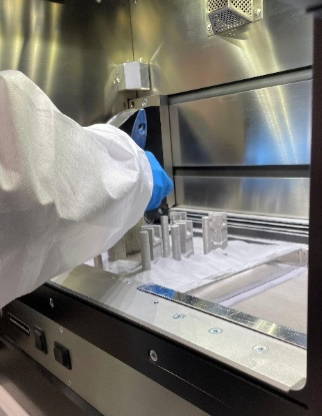
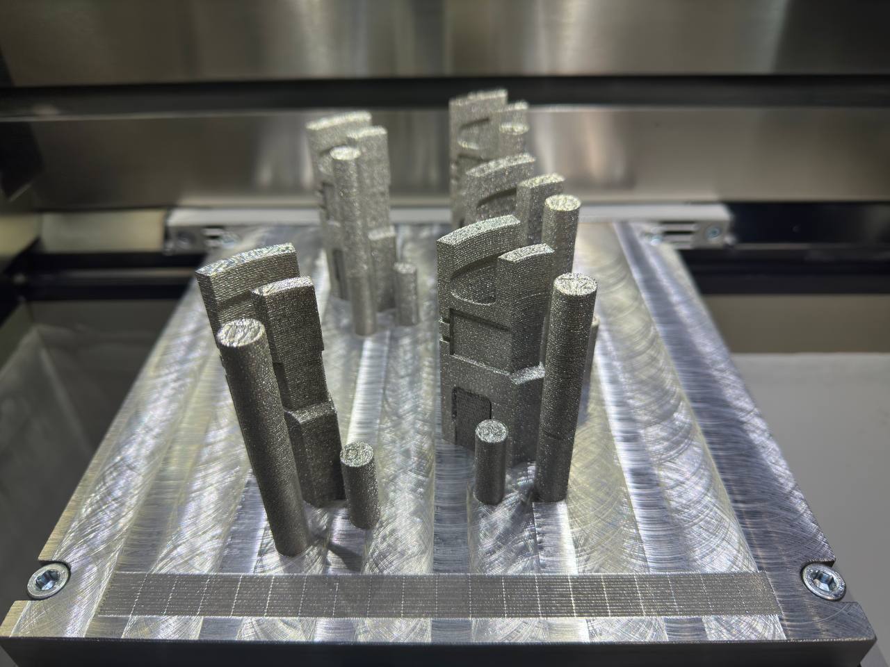
Figure 3. Depowdering of the build job and images of the first print of sections and coupons. Images: Federico Uriati/BEAMIT
The produced specimens will now be analyzed in Beamit’s laboratories to evaluate the effects of the different laser shapes on metallurgical properties, density, and surface quality. The preliminary results are very promising and it is expected that the implementation of these technologies in industrial production could lead to significant advantages in terms of productivity and savings.
This visit has allowed the Beamit team to deepen their knowledge of the advantages offered by the implementation of beam shaping in metal additive manufacturing. The results obtained are encouraging and pave the way for a future where metal 3D printing will be increasingly efficient, customizable, and sustainable. InShaPe’s overarching goal is to develop a novel first-time-right Powder Bed Fusion Process of Metals using Laser Beam (PBF-LB/M) that is not only more efficient but also significantly reduces waste and energy consumption, contributing to a greener manufacturing landscape.
Upcoming blog posts will present the results of the laboratory tests, providing a comprehensive analysis of the system performance metrics and reliability. Additionally, a discussion of the functionality and key features of the application will be included to highlight the advantages of the technology.

Gaussian, top hat or donut? Part I: Exploring the effect of beam shape on the productivity and density of additively manufactured AlSi10Mg.
The EU project InShaPe: Green Additive Manufacturing Innovative Beam Shaping and Process Monitoring aims at increasing the speed of laser powder bed fusion (PBF-LB/M) metal additive manufacturing (AM), while simultaneously reducing its cost and environmental impact. Three different materials, namely Inconel 718, CuCrNb and AlSi10Mg, have been investigated within the project.
PBF-LB/M is currently considered the most mature method within AM technologies. In this technique, a layer of metal powder of between 30 to 100 µm in thickness is deposited on a build platform and subsequently a laser is used to selectively melt certain areas, according to a digital model. This layer-by-layer process is repeated to produce near- or net shaped components.
The InShaPe beam shaping technology is expected to enhance the productivity of PBF-LB/M and concurrently make the process more adjustable and robust, as it can aid in heat distribution control within the process zone, which broadens the parameter window for material processing. Furthermore, this novel technology holds great potential for microstructural tailoring, so that specific sections of a component are customized using appropriate processing parameters. The beam shape has almost unlimited possibilities, as illustrated in Figure 1.

Figure 1. Beam shapes that can be achieved with the InShaPe system. Left: Gaussian beam shape. Right: Donut, Top hat and other novel beam shapes. Image: courtesy of EOS.
Although some beam shapes, e.g., donut, have shown promising results reducing defects and expanding the processing parameters window to produce AlSi10Mg1, no parameters have been established and optimized for laser powers above 800 W. Furthermore, a systematic evaluation of the effect of beam shapes on both density and productivity for the manufacturing of AlSi10Mg is a crucial step for the future development and optimization of this promising technology.
In February 2024, the initial trials were commenced in a joint effort between AMEXCI AB and EOS GmbH to investigate the effect of different beam shapes on the PBF-LB/M process build rate and porosity for AlSi10Mg. An EOS M 300-4 prototype with an integrated beam shaping system and maximum laser power of 1.3 kW was used.
In total, five distinct designs of experiments (DOEs) were conducted using layer thicknesses of 60 µm, 90 µm and 120 µm. In these DOEs, 10 mm cube specimens were produced using different combinations of beam spot size, hatch distance, laser power, laser speed and beam shapes. The specimens produced in one of the trials is shown in Figure 2.
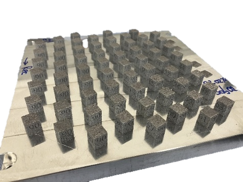

Figure 2. Left: 10 mm cube specimens produced with 90 µm layer thickness. Right: AMEXCI materials lab used for sample analysis. Images: Amit Saini/AMEXCI, AMEXCI Materials Lab Newsroom – AMEXCI.
The density of 180+ samples was evaluated using Archimedes principle, as shown in Figure 3. Based on the measured densities and the theoretical build rates, several samples from each layer thickness were selected for further porosity investigations with optical microscopy. The following Figure 3 and Figure 4 showcase how preparation of specimens for optical microscopy evaluation has been conducted at the materials lab.
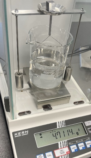

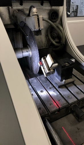

Figure 3. Density evaluation using Arquimedes principle and samples’ sectioning for optical microscopy investigations. Images: Merve Canalp and Victor Pacheco/AMEXCI.
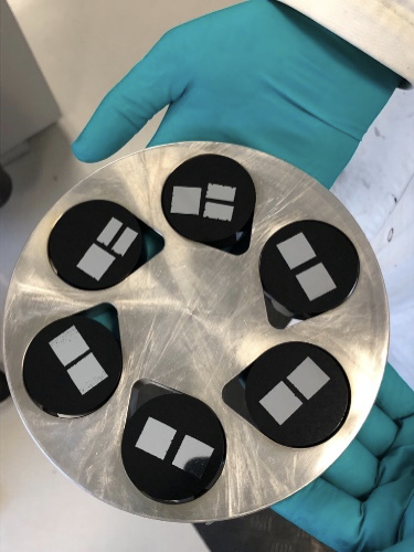
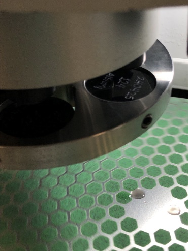
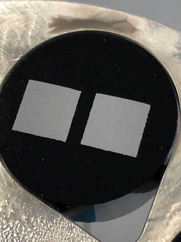
Figure 4. Preparation of selected specimens for optical microscopy evaluation through grinding and polishing. Images: Merve Canalp/AMEXCI.
The evaluation of selected specimens with optical microscopy has been recently finalized at AMEXCI Material Lab facilities. Based on the results, the next trials will be designed and implemented to establish parameters that provide both dense parts and high productivity in the manufacturing of AlSi10Mg with PBF-LB/M.
The development of parameters with a good balance between density and productivity is an essential step before upscaling and demonstrating the beam shaping technology for AlSi10Mg. This will be done in the future using AMEXCI’s use-case, which consists of a cylinder head for a chain saw. News and updates on the developments of this exciting project will follow in future blog posts. Stay tuned!
1 Tim Marten Wischeropp, Hussein Tarhini, Claus Emmelmann; Influence of laser beam profile on the selective laser melting process of AlSi10Mg. J. Laser Appl. 1 May 2020; 32 (2): 022059. https://doi.org/10.2351/7.0000100.