Leveraging the Benefits of Laser Beam Shaping on a Demonstrator Application
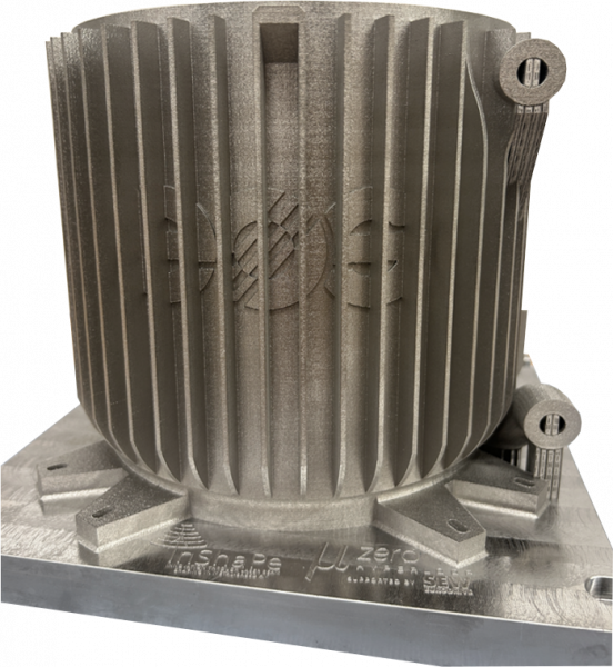
The technology developed within the EU project InShaPe enables new, application-optimized processing strategies for the additive manufacturing process Laser-based Powder Bed Fusion of metals (PBF-LB/M). These optimized strategies lead to significant benefits in key performance indicators such as productivity, energy consumption, material usage, and manufacturing costs. This is demonstrated in the following sections through an application demonstrator build job of a heat exchanger. The part geometry was kindly provided by “mu-zero | Hyperloop”. In addition to the heat exchanger, text and “feather” geometries are added to test detail resolution. The whole job layout is shown in Figure 1.
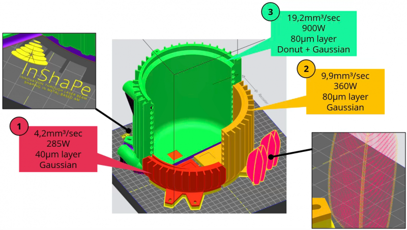
Figure 1: Job layout of the application demonstrator with parameter assignments.
Job setup
The material used is IN718. The primarily rotationally symmetric application geometry is divided into three segments, each assigned a different process parameter, as described in Table 1, allowing for direct visual comparison of the manufactured parts. The respective build heights of the segments reflect the nominal productivity of each parameter used: in a 30-hour build time, parameter 1 completes 25% of the part, parameter 2 completes 60%, and parameter 3 completes the entire part.
For parameter (3), a combination of a donut and Gaussian beam shape is used. The donut shape, with specific parameter properties, is employed for the bulk infill, while the Gaussian shape is used only for the part’s contour.
The job was built on an InShaPe EOS prototype system with a single laser, which allows for fast switching of the beam shape during the process. The build plate measures 250 x 250 mm2, and the job is 180 mm in height.
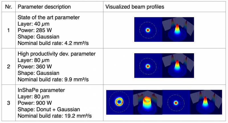
Table 1: Used process parameters
Manufacturing Process
As two different layer thicknesses, 40 µm and 80 µm, were combined in a single job, recoating occurred in 40 µm steps, with exposure of the 80 µm parameters performed only every second layer. Despite the high power, productivity, and large exposure areas, recoating was very smooth, even at a 40 µm layer thickness—typically an indicator of a stable, high-quality PBF-LB/M process. Figure 2 shows a powder bed image after exposure and after recoating, with a consistently applied powder layer.
Visible in Figure 2 (indicated by the green and orange circles), the productive InShaPe parameter (3) appears to produce fewer spatters than parameters (2) and (1) as can be seen by fewer “black dots” in the image. Spatters created by the laser-material interaction are typically ejected from the process zone, carried by the gas flow, and either fall back onto the powder bed downstream or are transported to the filtration system. For parameter (3), less material appears to be ejected, or the spatter morphology is more efficiently managed by the gas flow.
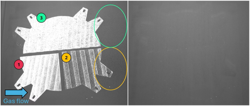
Figure 2: Powder bed image after exposure (left) and after recoating (right) early in the build job. The numbers indicate the assigned parameters.
Evaluation
The completed build job, shown in Figure 3, displays no obvious defects or visible differences between the three parameters.
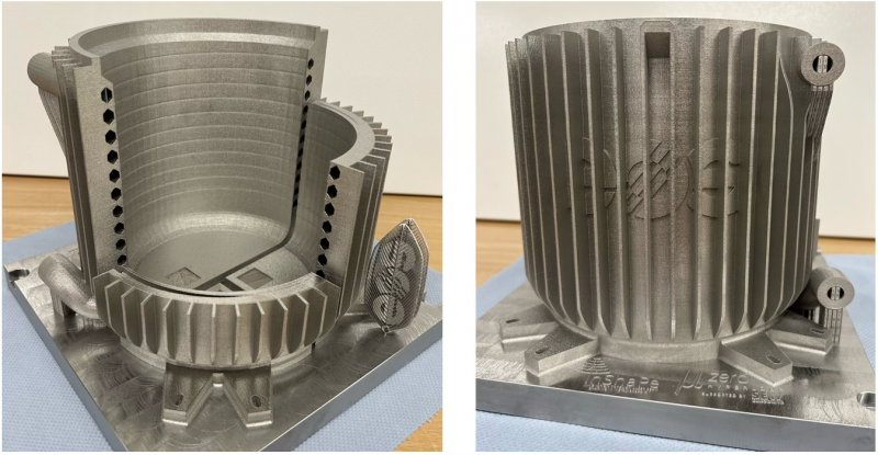
Figure 3: The manufactured parts shown from two sides
Figure 4 details the fine detail text, “feather” parts, and upskins of the three parameters. The fine detail parts were manufactured with a Gaussian beam, as they mainly consist of wall thicknesses down to 100 µm, requiring the highest resolution possible. All details were built successfully.
In the three upskin segments, rectangular “windows” into the part reveal areas where no upskin was applied, showing the “raw infill.” As observed, the InShaPe parameter (3) with its donut beam shape appears significantly rougher than the other parameters with a Gaussian beam. Focusing on the upskin, it is evident that a suitable combination of exposure strategies can mask the rougher appearing inskin, achieving an identical surface finish to that of the other 80 µm layer thickness parameter (2).
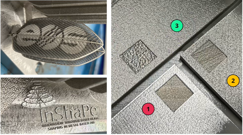
Figure 4: Fine detail geometries (left) and upskin regions (right)
Figure 5 shows a side- and downskin comparison of the build job. Here, the InShaPe parameter (3) produces the most shiny and homogeneous surface among all parameters. Interestingly, the detail of the cooling channels shows excellent geometric accuracy, even compared to the 40 µm layer thickness parameter (1). For parameter (3), the vertical walls are truly vertical, and the downskin regions are smooth and even, as intended.

Figure 5: Images of the side- and downskin regions and detailed image of the cooling channels.
Conclusion & Outlook
This demonstrator build job shows that beam shaping and the flexible use of various beam shapes allow for significant advantages:
- Compared to the current state-of-the-art parameter, a nominal build rate increase of approximately 4.6 times was achieved.
- Despite the higher layer thickness and the larger donut beam shape, there is no loss in geometric accuracy; instead, geometric accuracy even appears improved.
- Surface finish for the downskin was best with the InShaPe parameter and mostly unchanged for side- and upskins. The InShaPe parameter generally showed the most homogeneous surface morphology.
- Despite high laser power and build rate, the InShaPe parameter seems to emit fewer spatters than the Gaussian counterparts.
- Small features can be built effectively by switching to the Gaussian beam shape.
As this test primarily focused on the visual comparison of the three parameters, future investigations will also examine the material properties achieved. The analysis of spatter emissions is crucial for reducing material waste and improving the economic footprint of additive manufacturing.
Overall, the current results already look very promising and provide a solid foundation for further benchmarking the application demonstrator against the InShaPe KPIs of productivity, energy consumption, material usage, and manufacturing costs.
Authors: Markus Birg, Fabian Sonnen | EOS
All images: EOS